

FA1-NZRP-PCB-8 STEP
£5.99
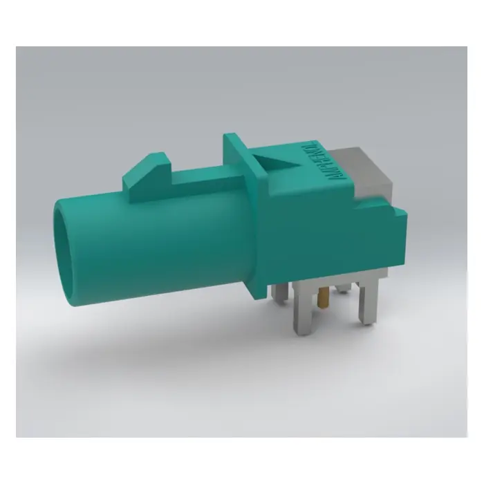
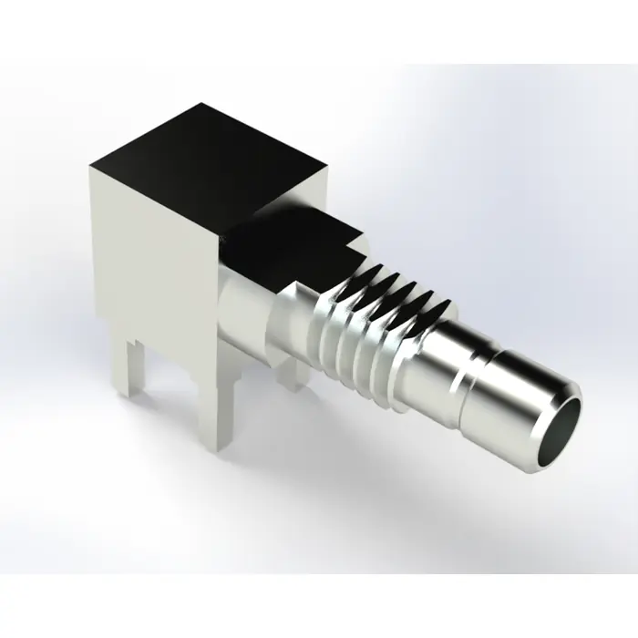
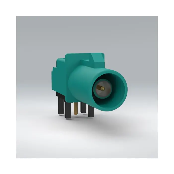
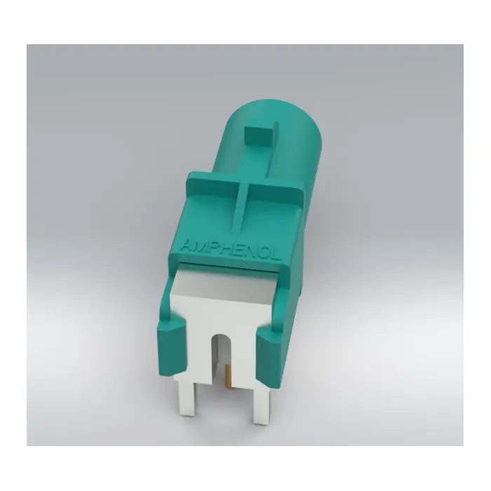
Detailed multi-body STEP model of the FA1-NZRP-PCB-8 RF connector, with all main 3D parts separated for individual material assignment. Ideal for RF and electromagnetic simulation, PCB integration, mechanical verification, and ECAD/MCAD library development.
Description
FA1-NZRP-PCB-8 Multi-Body STEP Model for RF Simulation
This product contains a detailed 3D STEP model of the FA1-NZRP-PCB-8 RF connector, specially prepared for electromagnetic and RF simulation applications.
Unlike the standard manufacturer model, which is typically supplied as a single combined solid body, this version includes the connector parts as separate 3D bodies.
This allows each part of the connector to be selected individually and assigned the correct material properties inside RF, electromagnetic, mechanical, or multiphysics simulation software.
The separated model structure makes it easier to identify and configure the metallic contacts, outer shield, internal dielectric parts, plastic housing, mounting features, and PCB terminals.
Main Features
- Detailed 3D model of the FA1-NZRP-PCB-8 connector
- STEP file format
- Multiple separate 3D bodies
- Suitable for individual material assignment
- Ideal for RF and electromagnetic simulation
- Useful for PCB mechanical verification
- Suitable for ECAD and MCAD integration
- Can be simplified or modified according to the simulation requirements
- Useful for technical documentation and rendered product images
Why Use a Multi-Body STEP Model?
Many manufacturer-supplied STEP models combine all connector parts into a single solid body. This can make RF simulation preparation difficult because different sections of the connector require different material properties.
With this multi-body version, the user can separately configure:
- Conductive contacts and PCB terminals
- Metallic shielding and structural parts
- Internal dielectric materials
- Plastic housing components
- Mounting and support features
Individual parts can also be hidden, removed, simplified, or modified when preparing the simulation model.
Suitable Applications
- RF connector simulation
- 3D electromagnetic analysis
- Material property assignment
- Signal integrity studies
- PCB connector placement verification
- Enclosure and mechanical clearance checks
- ECAD and MCAD library development
- Technical illustrations and product rendering
Download Contents
- FA1-NZRP-PCB-8 multi-body 3D STEP/STP file
- Connector parts provided as separate solid bodies
Important Information
This is a digital product only. No physical connector will be shipped.
The model should be verified by the user against the latest manufacturer documentation before being used for production, manufacturing, or critical mechanical applications.
Related products
-
-
-33%
- Connectors
A-DS 09 A/KG-T2S
- Original price was: £3.00.£2.00Current price is: £2.00.
- Add to basket
-
-33%

Reviews
There are no reviews yet.